Simple gate opener w/ imp?

Hi all, I’m sick of missing my amazon deliveries!

I live in a condo with a community gate and deliveries cannot get in. They would call me and I would be helpless at work.

Thus, I googled possible solutions and stumbled upon the Imp. Disclaimer: I know absolutely nothing about electronic circuitry or coding but this seems to be an answer. I was thinking of having the Imp open my gate remotely through either alexa or an iPhone app. Searching the forums I’ve seen many had done similar things but unfortunately they speak greek. So just checking if i am on the right track.

I plan on dismantling a control (uses generic Multicode remotes) and then hooking up the imp to press the button for me? As far as I can tell I should be able to do this with the Imp, an April board, and the gate control?

I just want to make sure I have parts, I’ll figure out rest after I get them in. Thanks in advance!

KD

Yes, the Imp could work great for this, and it’s fairly inexpensive. The main thing you need to do is make sure you have WiFi access at the location where the Imp is at (you say it will be with the remote control). That WiFi needs to be with a normal router typical of one you have in your house. Not captive WiFi like a business might use. You also have to make sure your gate remote actually works from where you will be setting it up (like in your condo).

Now the harder part …

You are providing a way to open the gate remotely. Do you have permission to do this? Does everyone else know that someone will be controlling it remotely? How will you know if the gate is opened or closed? The Imp is secure, but your ability to access it and perhaps showing other people how you do it would not be secure. The weak security issue is usually the human, not the machine. Since you will probably use your smartphone to operate the gate, will there by any passwords required? Can someone playing with your phone open that gate? The delivery person might come across a resident who asks them, “how did you get in?”. “Well, I called a guy and he said he would open the gate from his location.” The resident says, “Really?, that doesn’t seem right.”

The very best option would be to have physical sensors or switches on the gate itself so it would be known if the gate was closed, open, or ajar. That doesn’t seem like it would be possible in your case. Since the Imp is toggling a relay (the remote pushbutton switch) you won’t have any feedback and not know the status of the gate. You can’t see the gate from your remote location. So now you’re in a mode where you’ll be thinking, “Did I close it? Did I open it? I can’t remember how many times I pushed the button”.

When it comes down to the Imp itself, we can discuss the hardware more. Let us know what your thoughts are on all of this.

EDIT:
If you have trouble finding an Imp001/april board, you can get the Imp003:
https://www.digikey.com/product-detail/en/murata-electronics-north-america/IMP003-BREAKOUT/490-14054-ND/6205491

@ mlseim,

Thanks for the reply. The remote does indeed reach the gate from my location. I am not concerned with security or permission. When activated the gate opens then shuts on its own. Also residents all have buzzers to open the gate from within their homes.

Are the imp, april board, and a control all I will need for this project? Maybe a small circut board to place them on? Looks like lot of these projects have a 5v relay. Is that also needed? Will I also need any resistors or anything else? Asking because most, if not all, of these projects are more complicated than mine.

Thanks again!

Can you take a picture of the remote in question? (ideally, the inside)

Using a relay is the easiest, and relay boards are very cheap - you want one that’ll work with a 3.3v control signal (searching for raspberry pi will find compatible ones), eg https://www.amazon.com/SunFounder-Channel-Optocoupler-Expansion-Raspberry/dp/B00E0NTPP4

The relay board is 5v, so you can use the April’s VCC pin for that (assuming you’re powering it from 5v, then VCC is 5v). Wiring between the april and relay board would then be GND-GND, VCC-VCC and any imp pin to “IN1”, with the remote’s switch on the other side of the relay between the outer two terminals (going by the picture on amazon, these are the normally open pair).

@KD28,

Since you know little about electronics, there is something you need to do first. Get yourself a soldering iron, some solder and two small hook-up wires about a foot long each. Not sure where you’ll get these things, but maybe you have a friend or coworker that does some hobby stuff at home?

Open the remote, locate the switch and determine the two places on the circuit board where the remote control pushbutton switch is soldered on. Solder your two wires on the same two places, drill a small hole in the remote and extend them out of the plastic.

At this point, if you touch the two wires together or 1/2 second, the gate should open. You have wired the two wires in parallel with the pushbutton.

If you get to that point, now you can start putting together the Imp and other parts. I just want you to know that you will have to solder things … perhaps never doing that before, you may want to practice or get help.

Powering the Imp with a USB charger (5 VDC) is a good way to go. You can also buy cheap 5VDC miniature relays on Ebay. If that, then you’ll also need a transistor, couple of resistors, a diode and misc. hook-up stuff. I’ll try to find a photo of my Imp/remote garage door opener. The Imp closes the relay for 1/2 second … in parallel with the pushbutton on the wall of the garage.

@hugo has the correct answer to use a relay breakout board. This one can be driven by the imp pin directly.

@hugo

So, I’ve ordered the April Board, Electric Imp and this 5V relay Module: ttp://www.dx.com/p/arduino-5v-relay-module-blue-black-121354#.WiuDAUqnFhF couple days ago before the above replies. Hope they will work.

“The relay board is 5v, so you can use the April’s VCC pin for that (assuming you’re powering it from 5v, then VCC is 5v). Wiring between the april and relay board would then be GND-GND, VCC-VCC and any imp pin to “IN1”, with the remote’s switch on the other side of the relay between the outer two terminals (going by the picture on amazon, these are the normally open pair).” … HUH? lol I guess I’ll have to wait to get the parts, then hopefully it’ll make more sense.

@mlseim I was expecting to have to solder couple wires and that shouldnt be a problem. In terms of power, The April Board has USB in for power I can just use that no?

So, in layman’s terms. Sounds like the Imp gonna put out directions thru the April Board to the Relay which will trigger the circuit on the remote?

Thanks again guys. This is fun lol.

KD

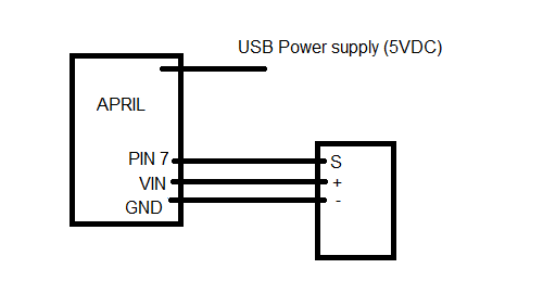
Yes, you will use a normal 5VDC USB power supply. The USB cable needs to be “USB Mini-B cable” connector.

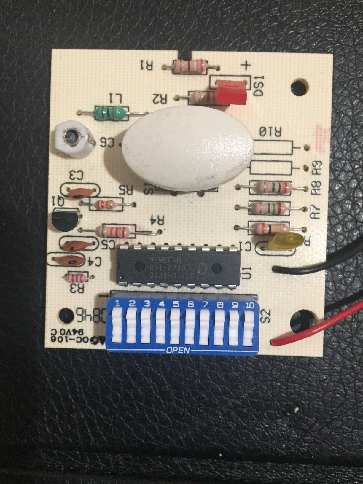
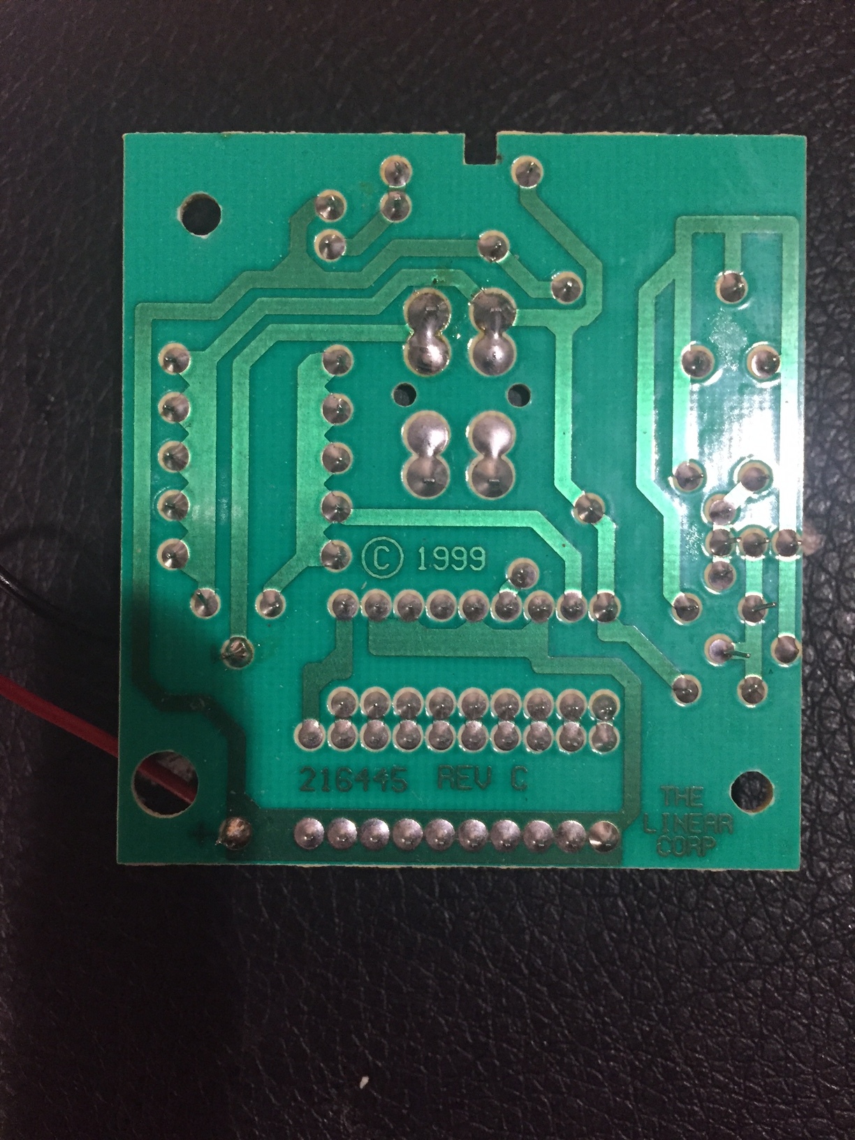
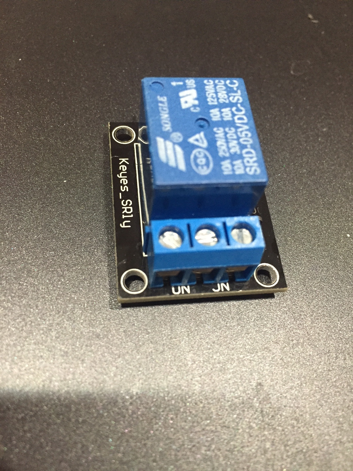
The Wires on your Remote Control:

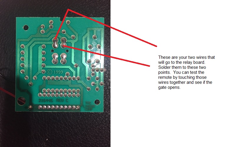
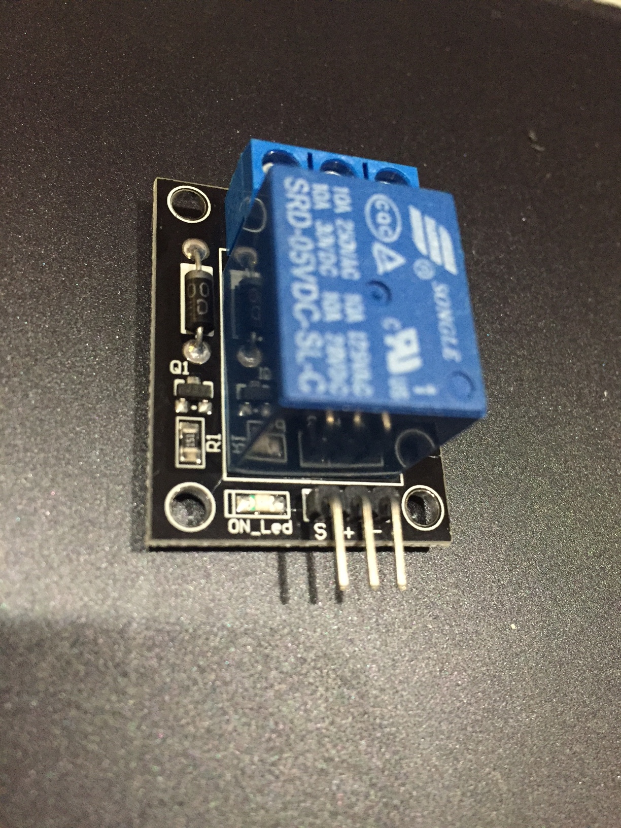
Solder the two wires as shown:

The programming:
You already have an Electric Imp account with user and password. You will download the free app for your smartphone (iphone, ipad, android). “Electric Imp Blinkup”. When you have your imp and that app, you will enter your account info into the app, pick your WiFi SSID from the list, enter your WiFi password and hold the phone facing the powered-up imp. It will “blink”, sending WiFi connection to the imp. An LED on the imp will flash different colors and eventually flash green as it successfully connects.

The programming will all be done online using the Electric Imp IDE. The imp will become a webhost and you will access it with a browser (on your phone, like Safari, Chrome, etc). You will have a URL or domain address like this: https://agent.electricimp.com/K_Ju4Ytb6MTh8

When you go to that URL (yours will be unique to your imp), you’ll see the web page you created with a button to open the gate. All of that part will need to be programmed by you of course.

If you want your own domain name, you would have to have your own webhost account with someone like GoDaddy. That costs money, but then you would be going to a website like: www.kd28.com

Once you successfully blink-up to your imp, we can direct you to some programming examples and imp coding. If you are able to learn the IDE (which is also a learning curve), you can have someone like me be a “collaborator” to your imp device. That way, I could view your imp code and assist without needing your login.

This is your first imp and your first electronic project. You will have to learn everything as you go and once you finish this project, the next one will be way easy. So don’t get frustrated with this … we can walk you through it.

There are youtube videos on doing the blinkup too, so view those when you get your imp and power it up for the first time.

Don’t touch any wires or put metal things near the imp and april board until you’re ready to connect the relay board to the imp. Applying voltages to imp pins improperly can damage the imp.

When you get your imp, april board, and USB power supply, you can insert the imp into the april board and connect the USB. Out of the box, the imp should flash some red and orange LED colors as it attempts to connect, which won’t be successful until you do the blinkup. But that will indicate to you that it is properly powered. The imp looks like an SD Card, but it’s not. Don’t put the imp into anything except the april board and don’t put an SD Card in the april board. Don’t let anyone else play with your imp and accidentally plug it into a PC.

NOTE:
I’m not sure what you paid for your imp and april board, but you can (in the future) buy the imp003 for $30 plus shipping:
https://www.digikey.com/product-detail/en/murata-electronics-north-america/IMP003-BREAKOUT/490-14054-ND/6205491

With that, you’ll get way more pins and it’s all one one board (no SD card packages). The imp003 board has the LEDs for blinkup and operates just like the imp001. The board footprint is really small too even though the board looks big on the photos. Just a thought if you get any ideas about future projects. This imp stuff is really addicting as you are noticing.

You probably saw this too …

This imp (The “explorer” via amazon) has some built-in sensors and RGB LED:
https://www.amazon.com/Electric-Imp-impExplorer-Kit/dp/B01N47J61L/ref=sr_1_1?ie=UTF8&qid=1512842454&sr=8-1&keywords=electric+imp

It’s not very expensive either, but you’re limited to the number of pins you can use. It’s the imp001 on a different board than the april board.

So for the money, getting the imp003 is the way better deal. Imp003 has about 23 I/O pins.

Hi guys,

I got my hardware in. I was able to flash the Imp and get it online. I have been able to the imp to respond. While I appreciate the help thusfar and know I’ll be needing alot more, I’m trying to figure out as much as I can because I find it fun.

Now for the questions. Can the April board provide power to the remote? Not that big a deal I can still use the 9v but was just curious. Any easy way to mount the April to a perf board? Just solder on?

Connections: I’ll be connecting

  • the GND on April to the ‘minus’ on relay

  • the VIN on April to the ‘plus’ on relay

  • pin 7 on relay to ‘signal’ on relay

  • either of the NO and the center from relay to the 2 points on remote pointed out above by @mlseim

In terms of the code. Trying to figure it out. I intend to have Amazon Alexa trigger the Imp through IFTTT (using webhooks channel). I’ve looked at other projects and tried to steal relevant parts but still not sure how to proceed.

Imp Device code: looks like this would press button and send log that its been pressed?

function pulseRelay()
{
hardware.pin7.write(1);
imp.sleep(0.5);
hardware.pin7.write(0);
}

agent.on(“buttonPressed”, function( value )
{
if( value )
{
server.log("HTTP: " + value );
local startIdx = value.find(“Button”);
server.log("IDX: " + startIdx );
if( startIdx != null )
{
pulseRelay();
}
}

});

hardware.pin7.configure(DIGITAL_OUT);

IFTTT part pretty straightforward - trigger phrase, make web request and give it the unique web address of my device. Is Agent Code Needed?

Thanks again for your help.

I’m not sure if pin 7 (3.3v) high will be enough, as it says 5V signal, but you can try it. You’ll be using a USB charger?(5vdc) The VIN will be the 5V coming in, do not use the 3.3V pin. So, 5vdc will be going to the + of the relay board.

You mentioned powering the remote also. If it were me, I would just leave it alone. Leave the 9V battery inside it and just have 2 wires coming out (from the pushbutton solder points). That way, you don’t modify the remote very much, and the remote button works as normal even if the imp is off.

keyes

Experiment and see if pin 7 can trigger the relay on the board.
It’s a transistor, so I think it should work.

Your device code is fine. That should work. IFTTT will be doing a POST to your agent URL with variable name and value. Example: data=Button

I’ll find some agent/device code I have … as I also use Alexa/IFTTT for a project.

The agent code would look something like this:

// Agent Code

myResponse <- "OK";

http.onrequest(function(req, resp){
if (req.method == "POST"){
local body = http.urldecode(req.body);
device.send("buttonPressed", body.data);
}
resp.send(200, myResponse );
});

On IFTTT, you will use the app that pertains to: If You say “Alexa trigger gate”, then make a web request. That app uses the key word “trigger”. When it hears “Alexa trigger gate”, it will make a web request to your agent URL and POST the variable and value:
URL: https://agent.electricimp.com/TH324Hy3453 (this would be your URL)
Method: POST
Content Type (optional): text/plain
Body (optional): data=Button

When you actually say outloud, “Alexa trigger gate”, she will respond “Sending that to IFTTT”. That’s all she will say. IFTTT will POST the variable to value to your agent, and the agent will send it to your device. data=Button
“data” is the variable, “Button” is the value.

Its me again! I’m trying to run test code to see if I am understanding the syntax correctly. Intention is to see if the agent can trigger the device. Looks like I’ve set up IFTTT and Alexa properly. My code is as follows:

// --------------------- AGENT CODE ------------------------

http.onrequest(function(req, resp){
if (req.method == “POST”)
{
local body = http.urldecode(req.body);
device.send(“trigger”, 0);
}
resp.send(200, “OK”);
});

// --------------------- DEVICE CODE ------------------------

function function1()
{
server.log(“Trigger1 Successful”);
}

function function2()
{
server.log(“Trigger2 Successful”);
}

function1();
agent.on(“trigger”, function2);

I am able to get the ‘Trigger 1 Successful’ message in my log. IDE doesnt like my ‘agent.on’ line in code of device. Tells me Error: callback must take 1 parameter in agent.on(msg, callback)

Function2 is where the agent would trigger my device to work right? Cant seem to get that line to work properly.

Thanks again!

You are sending the value of zero to the device on this line:
device.send(“trigger”, 0);

So in function2, try accepting a value (even though you don’t need to use it):
function function2(value)

// --------------------- AGENT CODE ------------------------

http.onrequest(function(req, resp){
 if (req.method == “POST”)
 {
local body = http.urldecode(req.body);
 device.send(“trigger”, 0);
 }
 resp.send(200, “OK”);
 });

// --------------------- DEVICE CODE ------------------------

function function1()
 {
 server.log(“Trigger1 Successful”);
 }

function function2(value)
 {
 hardware.pin7.write(1);
 imp.sleep(0.5);
 hardware.pin7.write(0);
 server.log(“Trigger2 Successful”);
 }

function1();
 agent.on(“trigger”, function2);

Some added comments about security …

Just say for example your Agent URL is https://agent.electricimp.com/TH324Hy3453

You are POSTing to that URL. When the agent gets the POST request it tells the device to pulse the relay. You are only concerned about getting the POST request without any other information.

If anyone in the world knows that URL, or accidently figures it out, they can POST to that as well and your gate will open.

It would be a little more secure if you actually POSTed a variable and value, example key=B5u8_RU201

With that, the agent will send that variable and value to the device and the device will compare it to its programmed key. If someone POSTed to your URL, they would also have to post that key. It just makes it harder to hack than doing a POST without a key.

Also, you are using Alexa. If someone can yell at Alexa through your door or window and Alexa can hear them, they can also open the gate. If you talk to someone in your condo about your project and you say that “phrase” in your discussion, Alexa might open the gate.

But perhaps in the end it’s no big deal if the gate opens. After all, it closes automatically and other people can open it as well. Nobody knows it was your Imp that opened it. Life goes on.

@mlseim

Everything has worked out. Thanks so much for your help w/ both the code and hardware. I really appreciate it.

In regards to your comments about security, in this case I am not too concerned but I do want to learn about adding a variable to the POST just so I would have an idea how to proceed in the future if I wanted slightly higher security. Where in the code do I specify that?

Some additional questions:

  • agent code line: local body = http.urldecode(req.body); isnt needed. Works fine without it. What exactly does it do?

  • Code is saved as a ‘draft’ (which obviously works fine). How do I save it as a template or a file? Is that what the ‘promote’ does?

Just curious, not big deal. So happy works as intended!

Thanks again!

That’s great! And the relay works too? And you soldered wires to the remote? Good job.

If you look back at this code:

// Agent Code

myResponse <- "OK";

http.onrequest(function(req, resp){
if (req.method == "POST"){
local body = http.urldecode(req.body);
device.send("trigger", body.data);
}
resp.send(200, myResponse );
});

You’ll see that it is expecting stuff in the body of the POST.
In this case, the variable is called data.

So with the IFTTT app, the POST data would be: data=B5u8_RU201

if you would rather use the variable name “key”, you would change a line in the agent code: device.send(“trigger”, body.key);

Then your IFTTT POST would be: key=B5u8_RU201

So the agent sends the variable and value to the device.
When the device function runs, you can see the value by doing this:

function function2(value)
 {
server.log(“Key: ” + value);
 hardware.pin7.write(1);
 imp.sleep(0.5);
 hardware.pin7.write(0);
 server.log(“Trigger2 Successful”);
 }

If you can’t get it to work, let me know.
It’s been a while since I’ve worked with this.

Be sure to use the tutorials they provide:
https://electricimp.com/docs/api/http/onrequest/

For saving code …
I just save a copy as a text file on my PC.
Just in case I lose it in the IDE or need it for some other purpose.
For me, I am just in “developer mode” at this time. Maybe someday I’ll be “blessed” with a real project.