Hello,
I am wiring a 2 wire motor for forward and reverse. It will run forward until limit switch then reverse to limit switch with x amount of time between cycles. I purchased a controller with timer that has 2 relays installed on the pcb. I am attaching a diagram of what I am working with because for the life of me I cant figure out how to wire this up to get the results i want.
Your image doesn’t show.
Oh, I guess it does when I click on it.
Tell us more about the PCB …
Where you got it, what the voltages are.
Are you using a DC motor (like 12VDC or 24VDC?).
Reversing a DC motor direction would be best using a Double Pole relay. Your board has 2 Single Pole relays. It would take both those relays just to do the direction change. Another relay would be needed for control power. That’s why we need to know more about the PCB
You posted this on an Imp forum … with transistors, a couple switches, and a couple relays, the Imp could do it all without your PCB. 2 Inputs, 2 Outputs. The Imp would do the timing and allow you to adjust or manually activate through the imp (internet controlled). Also, you would have feedback on motor direction.
Tell us more about the PCB
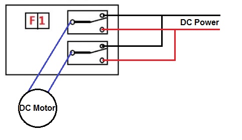
… Direction Control using 2 relays:
(both relays MUST switch at the same time, or you will short-out your power supply) …
mlseim that seems a bit dangerous, being so close to shortening it out.
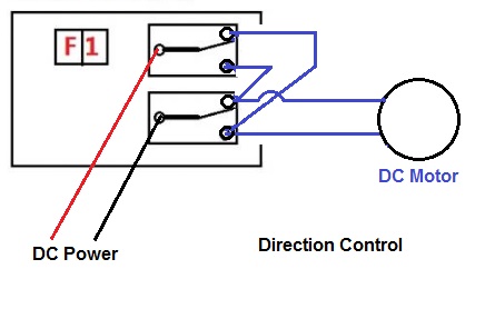
Instead attach one wire from the motor to the common pin on each relay, and negative on NC, and positive on NO, on both relays.
When both relays are released, negative will be send to both wires on the motor, and nothing will happen. Pull one relay, and it will switch that, and send positive on one wire to the motor, and still negative on the other.
No way to short it out, worst thing to happen is to pull both relays, and send positive on both wires to the more, and nothing will happen. 
So using this picture

Negative from the power supply attached to NC1 and NC2
Positive from the poser supply attached to NO1 and NO2
One wire from the motor to COM1, and the other wire from the motor to COM2
That’s why he should use a DPDT (double pole) relay, but it appears the PCB doesn’t have one. I would throw away the PCB and use my own components with Imp control.
It would be interesting to see what the PCB really is, and where he bought it.
Not enough information at this point. I also see no reason why he couldn’t unsolder one of those single pole relays and replace it with a double pole relay. Glue it upside down and hand wire/solder to the relay pins.
Double pole isn’t needed when there is two single pole, with two single, wired the way I was showing, you got both directions, and start and stop function.
Below is the revised wiring per @MikeyDK.
I agree that this is a much better way.