On the Imp005 breakout want to connect the u.FL. The description is as follows:
“An on-board u.FL connector is also provided if you wish to use an alternate antenna; to use this you need to remove R22 and stuff R23 to reroute the RF trace to the connector.”
This is the correct action - R22 and R23 are two footprints which share a pad; this is to prevent a stub in the RF trace no matter which way you route the RF signal.
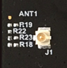
Hard to see with a black component on a black PCB, but R22’s top pad is to the left of the “R22” silkscreen, and the bottom pad is shared with R23’s left pad. So, you’d remove R22 and flip it 90 degrees clockwise to bridge R23’s pads instead, routing the RF signal to the u.FL connector.