Please can anyone point me in the right direction for how much current the imp005 I/O’s are able to source?
I was hoping to drive one of these directly from the I/O’s but the they have an onboard led and an opto so I’m guessing its going to draw around 10-15ma which I’m guessing will be way over what its capable of.
Look closer at the specs of your relay board. I believe that you have 2 power sources. The first one is the VCC for the relay side of the optic isolators. For that you can use 5VDC. The other VCC (on the row of input pins) would be the 3.3V VCC that the imp uses. The opto isolators are the separation. I also believe that the opto isolators are designed such that they float high (the relays are off). If you sink the pins to ground, the relay turns on. This logic might seem backwards from what you would think: 0=relay on, 1=relay off
The imp pins can sink current much more than source. So I would not think it’s a problem. In my opinion, it’s always better to sink a floating high, than to source. Larger loads might require a basic 2N222 NPN switching transistor.
The whole point to this board is the optic isolators. They control the relays with a larger current 5VDC VCC and isolate that from the lower current digital input pins.
But, let Hugo answer too … I would hate to have given a wrong answer and things go bad.
… I have burned-up an Imp before, it’s not fun … [sigh]
The relay board, as @mlseim says, is opto isolated. It looks like the control pins go through a 1k resistor (I can see a 102 marking) and possibly both the external LED and the isolator in series. Isolators use IR LEDs with ~1.3v drop, and assuming a 1.7v red LED externally you’re looking at 300uA (3.3-1.3-1.7 = 0.3, 0.3/1000 ohms = 0.3mA or 300uA).
You may find that this relay board is not going to work as it needs more than 300uA current, but it won’t hurt the imp.
You can try without the imp just by connecting the 3.3v breakout supply to one of the inputs and seeing if the relay switches. If not, there definitely ARE 8-relay boards which will work from 3.3v - look for “raspberry pi compatible” or similar in the description.
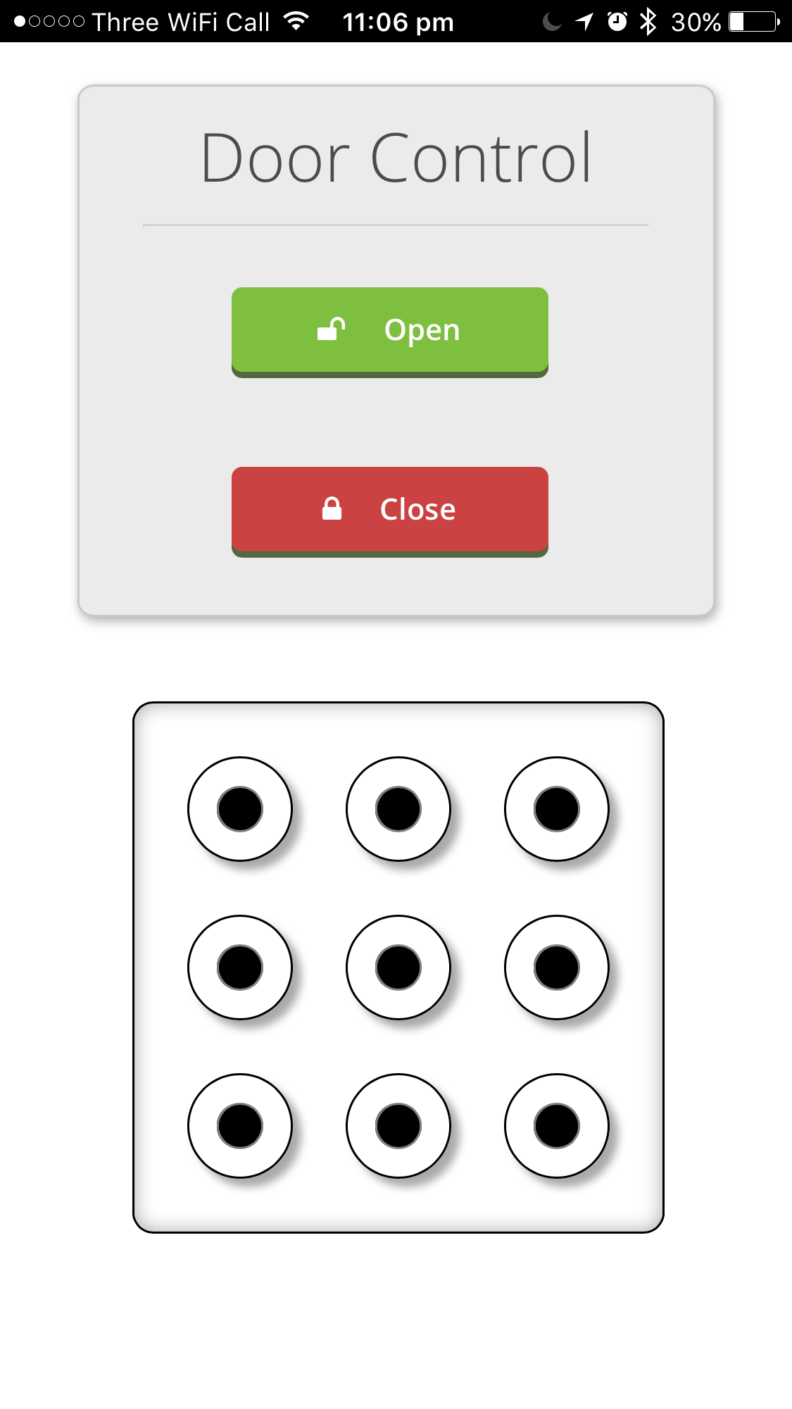
The interface is generated completely from the agent, even the home screen icon is stored in the agent code (base64 encoded), apart from the jQuery library all the style sheets and JS files are served from the agent.
You have to draw a pattern to enable the controls to stop people from accidentally opening the door from the other side of the world, i need to connect the door power supply to our alarm panel so its disconnected when the alarm is set, just in case…