The problem is when the motor is on, it’s causing a lot of instability within Imp. For ex: I have a few GPIOs that I configure as INPUT, and some GPIOs that I configure as OUTPUT. Without doing anything else other than turning on the motor, the Imp is detecting inputs in the INPUT GPIOs and I can also see that some output GPIOs toggle as well. In addition, the imp also restarts several times.
This seems to be pointing to a voltage or current spike issue when the motor is on and it somehow causes an issue with the Imp.
A few things I have tried/note:
The motor is rated to work from 1.5V and it’s consuming ~0.5A current, so this is not an issue of over current/voltage
A lot of ringing in motor supply causing issue with Imp -> I tried putting a ton of bypass capacitors on both supply leads and that didn’t help.
I tried adding diode across the motor
I also tried separating the power supply themselves where the motor is powered by 2x AA batteries. However since the GND of AA batteries & GND of Imp is connected, the instability is still there. (If I don’t connect the GNDs together, the switch won’t work)
I’m going to try a different (hopefully smaller) motor, but I’m quickly running out of ideas. If anyone can help provide any suggestion, it would be greatly appreciated!
Update: Using a smaller/different motor didn’t help. I
Using a load switch for the motor, like a Texas Instruments TPS22918 could help isolate the imp from the motor. There is also a specialized load switch for inductive loads On Semiconductor NUD3105. Or a low voltage motor dirver Texas Instruments DRV8830.
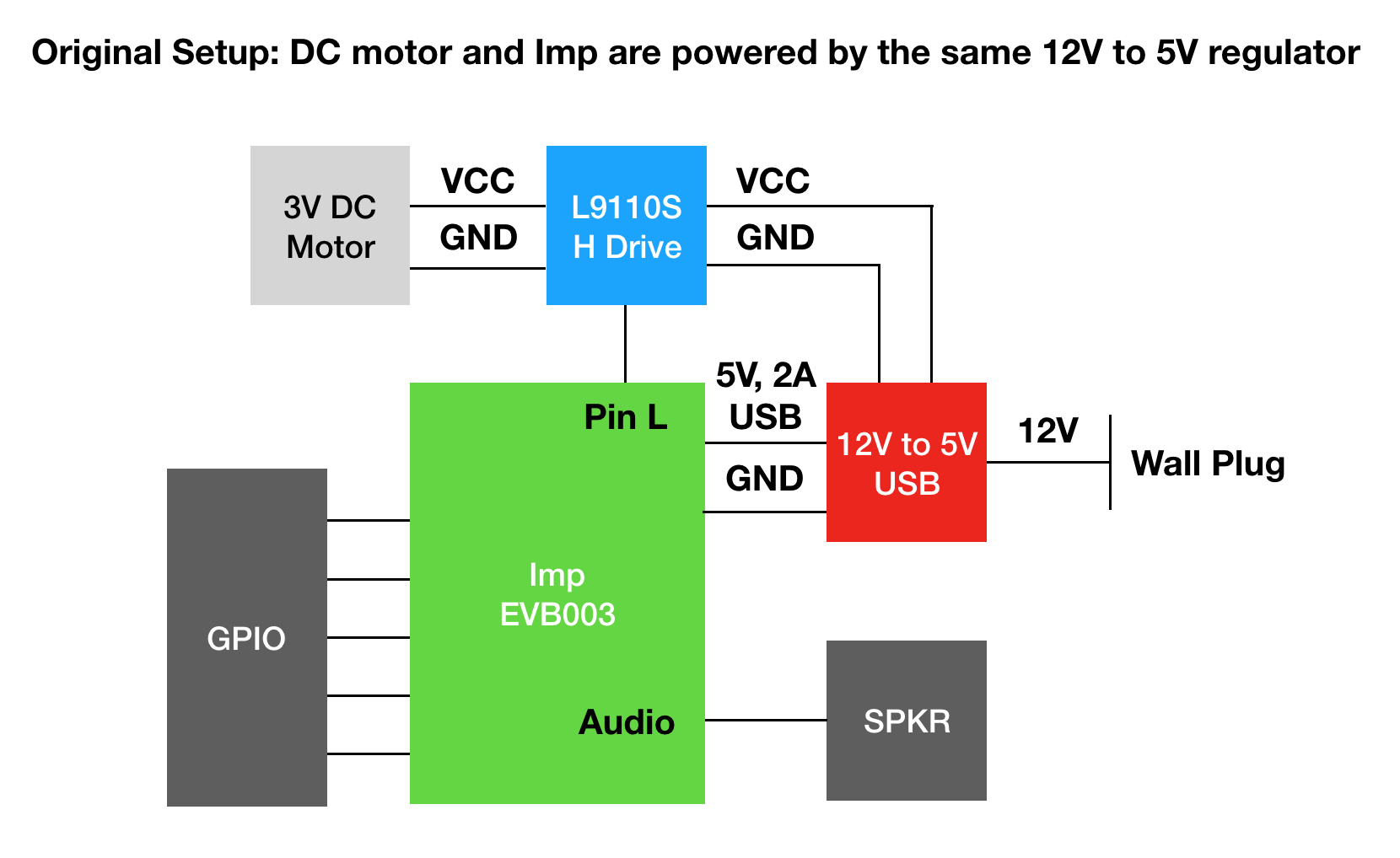
Here’s a couple of diagrams of my setup. I tried both. In the second diagram I try to separate the power supply to isolate the voltage/current spike from the motor to the Imp, but I can still see the issue. (The only lines connecting motor to Imp are the GND and Pin L)
How physically close is the motor to the actual imp?
I wonder if it is messing with the imp internal … DC motors spark w/brushes on the commutator, possibly bombarding with electro-magnetic interference. Experiment by moving motor far away or dropping it into a metal box/shield.
Thanks miseim. Yes I also saw the EMI signal causing issue with Imp. I tried completely severing the connection between motor and Imp, and then power up the motor completely independently of Imp. I noticed exactly the EMI issue you were talking about.
If I have the DC motor close to Imp (say within 5 inches) then the issue occured. If I bring the motor farther away the issue goes away.
However, I then try just connecting the GND together, and the issue happened again regardless of how far I place the motor away. (I must have the GND and 1 GPIO connected to the motor to control it).
induced voltages from the magnetic field. This is semi-unlikely; 5 inches is a long way and this would only couple to high impedance signals (eg floating/open-drain inputs) vs low impedance outputs.
“Ground bounce” which is essentially where the inductance of the ground path causes ground to move (relative to the signals) when there’s a large change in current. This can cause what appear to be input or output toggles, but in fact the signals are not moving - just the ground being used to interpret them is.
Addressing the biggest issue first, the imp rebooting - does it reboot when the motor is powered from battery? If not, then you have a power supply issue.
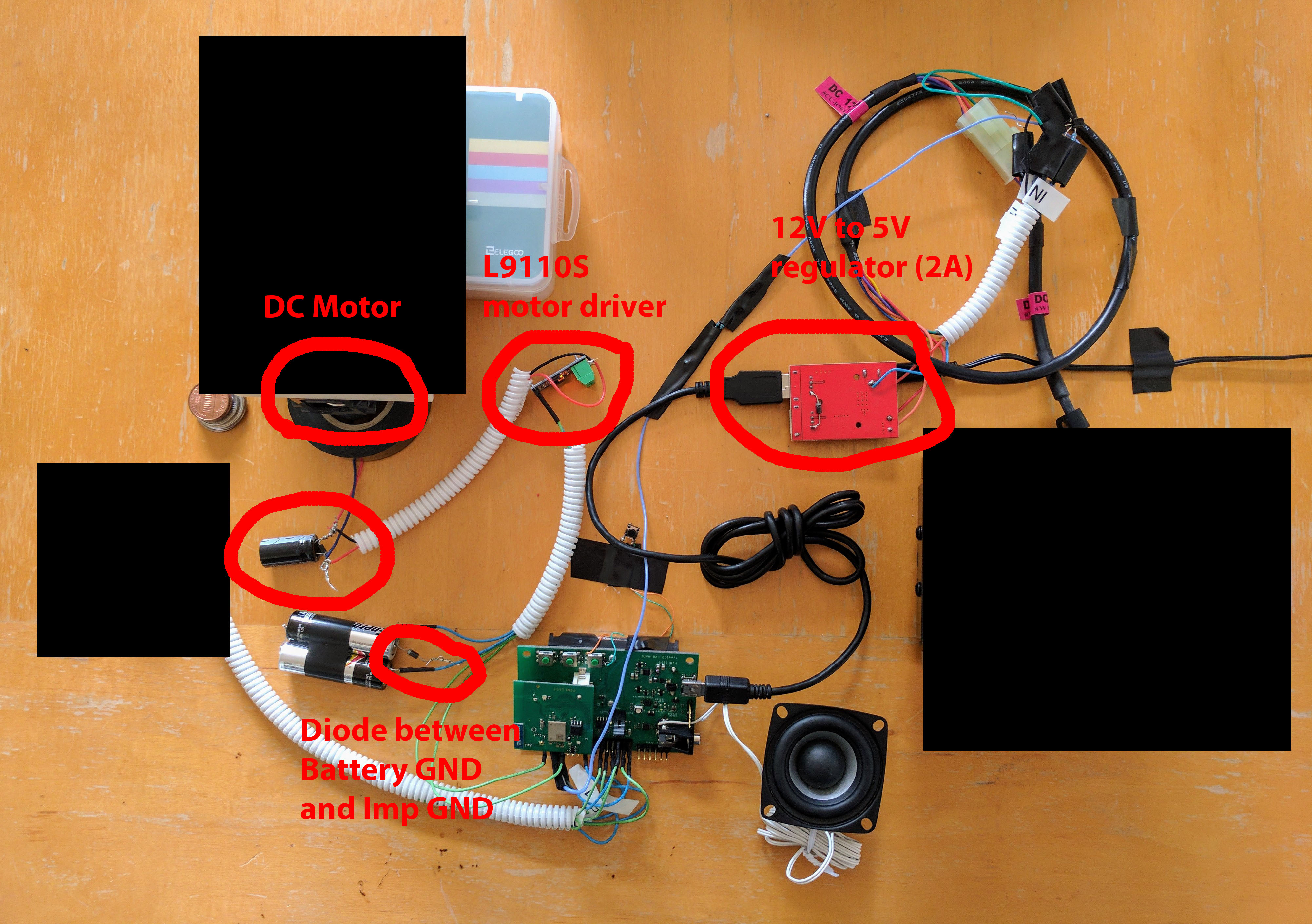
What are the GPIOs connected to? How are those connections grounded? Often these type of issues are only seen when you’re breadboarding things because all those wires & connections are awful for inductance. The diagrams are very pretty, but the reason I asked for a picture was more to see what the wiring looked like
Currently I have the motor powered by the battery and it no longer reboots when the motor’s on. (It still has the second issue where IMP is reporting input signals where there are none).
I definitely saw this issue. I separated the motor to the imp completely by powering the motor from battery, and turning it on/off directly from the battery itself. (There’s no connection whatsoever between the motor and the imp). I could clearly see that by placing the motor closer (~5 inches or less) the false inputs were detected. (5 inches or more, and the issue wasn’t present). As I need to put the motor and Imp board fairly close to each other in my product, I’m going to try making a crude RF shield to help with this EMI issue.
I tried adding a diode between the GND going to the motor and the GND going to IMP and that seems to help. I then added a big bypass cap (4700uF) across the motor + and - and voila, the issue is gone! So it looks like a big cause is the ground bounce that you mentioned. (Note that this issue is gone only when the motor is powered from the battery. If I power the motor back from the 12V to 5V regulator, the issue is still there even with diode and 4700uF bypass cap). Do you have a good recommendation on what to do for the ground bounce issue?
I use these devices for energy conservation. It allows me to shut down connected peripherals (like radios) when not needed and puts a very low demand on the imp’s gpios. I have not experienced your situation, but thought it would be a useful consideration.
Generally you should not put any extra inductance (eg a choke) in ground paths. You want to tie everything together as solidly as possible. A diode in a ground path is scary, to be honest.
The cap across the motor is a bit scary if you’re ever planning to run the motor backwards (as it’ll be reverse polarity, and that’s a polarized cap).
In this case, getting a big plain copper-clad board and using that as ground (soldering all grounds of all the subsystems - motor drivers, battery supply, power supply, imp, etc) to this board will help immensely. This is then closest to what happens if you make an actual PCB for the project.
Thanks Hugo, the setup is being used for demo at the moment. I’ll have it back next week and will try to use a copper sheet as common ground and let you know. Have a great weekend!
I removed the cap across the motor (even though it’s always going to be running in 1 direction, I agree that it’s dangerous as it’s polarized), removed diodes, and replaced them with a copper clad board plus grounding everything to it, and voila the issue goes away Thanks a lot for your help Hugo!!