Imp node with CO2 sensor

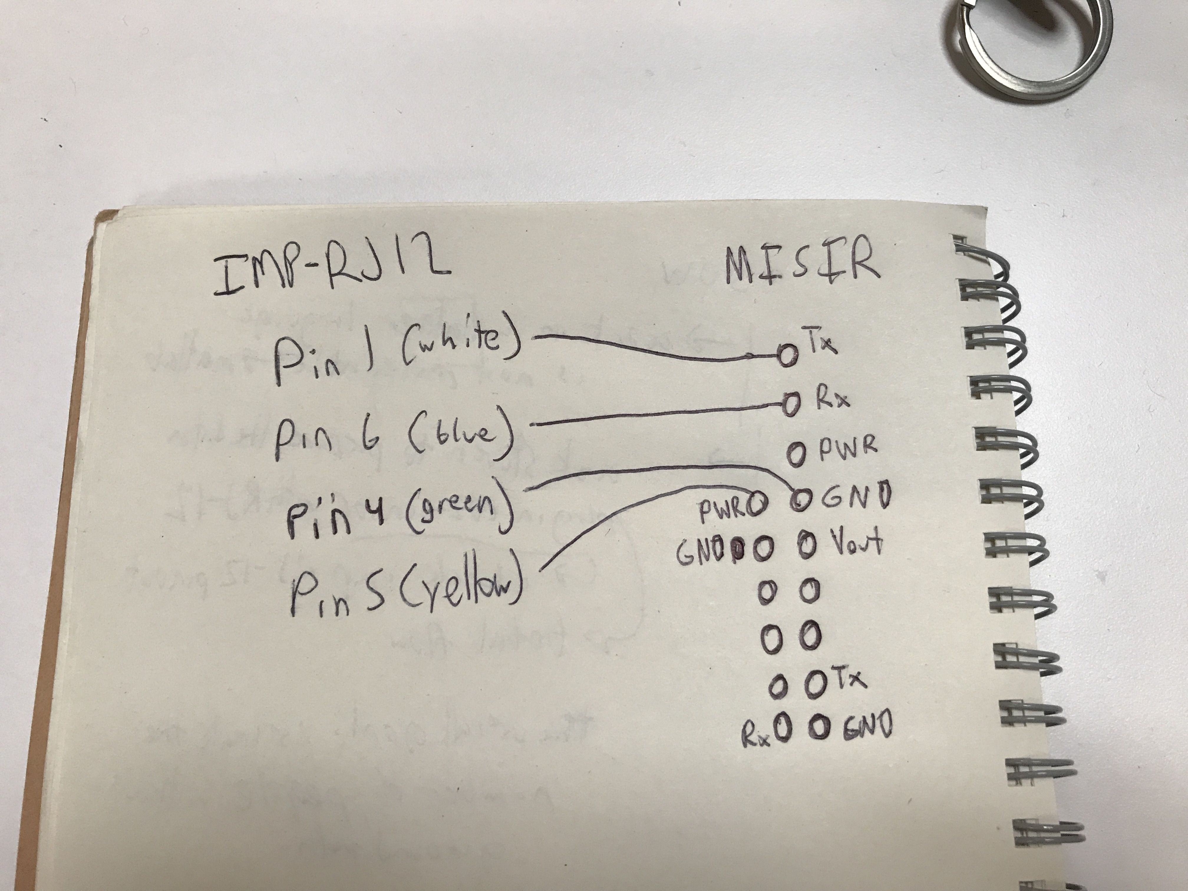
We are connecting a CO2 sensor with the RJ12 connector.

The imp that we are using is the battery powered sensor node which uses imp003
https://electricimp.com/docs/hardware/resources/reference-designs/sensornode/

This is the MISIR CO2 sensor sensor we are using.
http://www.co2meters.com/Documentation/Manuals/Manual-GSS-Sensors.pdf

Datasheet:

The callback function doesn’t get call. However, when we write a command(from the manual above), the callback is triggered and has return some value like 240, 224 or 0.

Please help us read the sensor, this is our first time encountering UART.

Thanks.

Here is the code that we are using.

local MISIR = hardware.uartFG;
local msg = “”;

function readMISIR() {
//local c = MISIR.read();
//server.log©;

//Pull a byte from the UART FIFO

local c = MISIR.read();

// Determine if this byte is a carriage return (triggers to log the line)
if (c == ‘\n’){

// Transmit message to the server
server.log(msg)

// Clear the message buffer
msg = "";

}
else{
// Accumulate the message string
msg=msg+format("%c",c);
}
server.log(msg);
}

imp.setpoweren(true);
local state = 1
hardware.pinY.configure(DIGITAL_OUT, state);
hardware.pinS.write(1);
MISIR.configure(9600, 8, PARITY_NONE, 1, NO_CTSRTS, readMISIR);
MISIR.write(“Z\r\n”);

So - pinS is not being configured as an output, which likely means the RJ11 power is not being turned on.

On the MISIR sensor, the docs indicate that it’ll just send all the time (without being asked) in default mode, so you shouldn’t need to write anything to it.

Can you draw a picture of, or otherwise indicate how you’ve wired the device to the RJ11?

I tried to configure the pinS with this line of code, state is 1
hardware.pinS.configure(DIGITAL_OUT, state);

The sensor is still not reading anything.

This is how we wired the sensor.
Pin 5 of RJ12 is power. Pin 4 is ground. Pins 1 and 6 are TX and RX.

I wonder if the configuration of pinS is done correctly.

Thanks

Using hardware.pinS.configure(DIGITAL_OUT, state); is correct - before you just wrote the pin, but by default all pins are configured as inputs so this would have had no effect.

Can you attach a picture of your wiring? Would like to check you have pin1 at the right end. Have you checked the power is enabled with a multimeter on the sensor end?

Hugo,

I just measured voltage out from pin 5 (power) and pin 4 (ground) from RJ12 and I measured 3.28 V when hardware.pinS.write(1) and 40-60 mV when hardware.pinS.write(0). I had hardware.pinS.configure(DIGITAL_OUT, 1) throughout. See attached image of wiring configuration. Still getting nothing from sensor. When we write to UART it returns 240, 224 or 248 regardless of whether or not pinS is powered up. The sensor did provide readings using the same pins using an Arduino board about a month ago.;

You have TX and RX the wrong way round; swap pins 1 & 6

TX is an output on the MISIR, and also an output on the imp. When you connect two UARTs together, you need to connect TX to RX and vice-versa.

Try that?

Excellent thank you!

Did it work then? Dying to know!

Yes, we are able to read! Now we are working on writing to the device to configure it.