Hi! I’m using an MCP23008, it works “sometimes”. That means that I get a lot of “I2C Read Failure” errors, about half the times the read function is called… the other half of the calls it works… it’s a very very strange behaviour, it’s like something is out of sync… I really am not able to debug this problem, can someone help me? Am I doing something wrong?
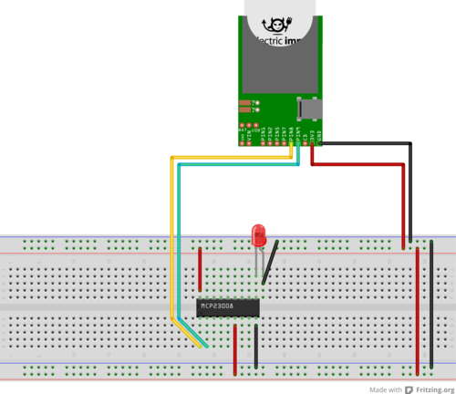
This is the connection scheme
and this is the code:
`// Base class for MCP23008 and MCP23017 family of I2C i/o expanders
class MCP230xx {
BASE_ADDR = 0x20
i2cPort = null
i2cAddr = null
regs = null
constructor(i2cPort, deviceAddr) {
    this.i2cPort = i2cPort
    this.i2cAddr = (BASE_ADDR + deviceAddr) << 1
}

// Read a byte
function read(reg) {
    local data = i2cPort.read(i2cAddr, format("%c", reg), 1)
    if(data == null) {
        server.log("I2C Read Failure")
        return -1
    }
    return data[0]
}

// Write a byte
function write(reg, data) {
    i2cPort.write(i2cAddr, format("%c%c", reg, data))
}

// Set/clear a bit in a register
function writeBit(reg, bitn, level) {
    local value = read(reg)
    value = (level == 0) ? (value & ~(1 << bitn)) : (value | (1 << bitn))
    write(reg, value)
}

function setValueForRegister(gpio, reg, value) {
    writeBit(regs[reg], gpio & 7, value)
}

function getValueForRegister(gpio, reg) {
    return (read(regs[reg]) & (1 << (gpio & 7))) ? 1 : 0
}

function setDir(gpio, input) {
    setValueForRegister(gpio, "IODIR", input ? 1 : 0)
}

function setPullUp(gpio, pull_up) {
    setValueForRegister(gpio, "GPPU", pull_up ? 1 : 0)
}

function setPin(gpio, level) {
    setValueForRegister(gpio, "GPIO", level ? 1 : 0)
}

function getPin(gpio) {
    return getValueForRegister(gpio, "GPIO")
}
}
// This class is compatible with the general Pin class
class MCP230xxPin {
device = null
gpio = null
regs = null
constructor(device, gpio, regs) {
    this.device = device
    this.gpio = gpio
    this.regs = regs
}
function configure(mode) {
    device.regs = regs
    switch(mode) {
        case DIGITAL_IN:
            device.setDir(gpio, 1)
            device.setPullUp(gpio, 0)
            break
        case DIGITAL_IN_PULLUP:
            device.setDir(gpio, 1)
            device.setPullUp(gpio, 1)
            break
        case DIGITAL_OUT:
            device.setDir(gpio, 0)
            device.setPullUp(gpio, 0)
            break
        default:
            server.log("MCP230xxPin: Invalid mode")
    }
}
function read() {
    device.regs = regs
    return device.getPin(gpio)
}
function write(level) {
    device.regs = regs
    device.setPin(gpio, level)
}
}
// Encapsulates a MCP23008 I2C i/o expander
class MCP23008 extends MCP230xx {
REGS = {
IODIR = 0x00
IOPOL = 0x01
GPINTEN = 0x02
DEFVAL = 0x03
INTCON = 0x04
IOCON = 0x05
GPPU = 0x06
INTF = 0x07
INTCAP = 0x08
GPIO = 0x09
OLAT = 0x0A
}
pin1 = null
pin2 = null
pin3 = null
pin4 = null
pin5 = null
pin6 = null
pin7 = null
pin8 = null
constructor(i2cPort, deviceAddr) {
    base.constructor(i2cPort, deviceAddr)
    for(local gpio = 1; gpio <= 8; gpio++) {
        this["pin" + gpio] = MCP230xxPin(this, gpio - 1, REGS)
    }
}
}
// Encapsulates a MCP23017 I2C i/o expander
class MCP23017 extends MCP230xx {
A = {
REGS = {
IODIR = 0x00
IOPOL = 0x02
GPINTEN = 0x04
DEFVAL = 0x06
INTCON = 0x08
IOCON = 0x0A
GPPU = 0x0C
INTF = 0x0E
INTCAP = 0x10
GPIO = 0x12
OLAT = 0x14
}
pin1 = null
pin2 = null
pin3 = null
pin4 = null
pin5 = null
pin6 = null
pin7 = null
pin8 = null
}
B = {
REGS = {
IODIR = 0x01
IOPOL = 0x03
GPINTEN = 0x05
DEFVAL = 0x07
INTCON = 0x09
IOCON = 0x0B
GPPU = 0x0D
INTF = 0x0F
INTCAP = 0x11
GPIO = 0x13
OLAT = 0x15
}
pin1 = null
pin2 = null
pin3 = null
pin4 = null
pin5 = null
pin6 = null
pin7 = null
pin8 = null
}
constructor(i2cPort, deviceAddr) {
    base.constructor(i2cPort, deviceAddr)
    for(local gpio = 1; gpio <= 8; gpio++) {
        A["pin" + gpio] = MCP230xxPin(this, gpio - 1, A.REGS)
        B["pin" + gpio] = MCP230xxPin(this, gpio - 1, B.REGS)
    }
}
}
// Example using two MCP23008 and one MCP23017 on the same I2C bus (using pins 8,9)
imp.configure(“MCP230xx Demo”, [], [])
// Configure I2C bus
hardware.i2c89.configure(CLOCK_SPEED_100_KHZ)
// Create i/o port instances (note: each device on the same bus should have a different device address)
port1 <- MCP23008(hardware.i2c89, 0) // pinstrapped to device address 0
// Assign leds to port pins
led1 <- port1.pin1 // MCP23008 has pin1 to pin8
// Configure pins as output
led1.configure(DIGITAL_OUT)
function run1() {
imp.wakeup(1, run1)
led1.write(1 - led1.read())
}
// Start
run1()`


