Hi,
I’m completely new to electric imp! I have the first “blink” example working, but only with a cable between the breakout board and my laptop. Of course Electric Imp makes no sense if you have a cable running to your computer.
I have read some articles about connecting a battery but most are very technical, without illustrations.
I’m looking for a simple newbie-schematic (perhaps make with fritzing, so that even beginners can understand what’s going on).
Its easy! All you need is a battery holder with leads, and the appropriate batteries. Many of these, like this one, are available at RadioShack, if you are in the US.
Just solder the leads to the P+,P- pads on the side of the breakout board. Red to P+, and Black to P-.
Your battery pack needs to be able to output at least 3.6V, so for example, you could use a 9V battery, or 3AAA (1.5V x 3 = 4.5V). Just make sure you don’t use over 17V, and to be very safe, I would stay at 12V or under.
Thanks!
Eerk,
Realize that you can’t run the imp for very long on batteries unless you really get into the “sleep” programming. You could also use the +5 VDC of a USB cable “wall wart”. You’ll be plugged into the wall, but not a computer. If you are going to be switching small relays, you’ll be forced to use a larger power supply of some kind anyhow, depending on the relays you’re controlling.
It’s great you’re getting interested in electronics, especially with the imp. It’s very addicting stuff. If you ever doubt your connections or components, be sure to ask here first … I’d hate to have you burn out a pin on the imp.
I thought the whole point of the Imp was to make a device completely wireless 
A wall plug may be the next best thing, do you have an amazon link for one that would work? I am in the Netherlands, meaning it has to be 220Volt.
The imp has to be within a WiFi area, so it most likely will be inside something that already has power … an appliance, vending machine, a garage, basement, utility room, etc.
Anything like this would work:
Use a wall-wart for power while you’re developing, and then remove it and switch to battery later on if you wish. There are no rules about how to use the imp. It all depends on what your project is supposed to do. The amp rating of the USB charger needs to be able to handle your load. 500ma to 1amp range is typical.
Note,
You’re not in the U.S., but there are companies like this one (link below) that sell open-sourced imp boards for various uses. Notice on this one how they use a 5VDC 1amp USB charger for power. That’s exactly what I’ve used on some projects:
Thanks for the elaborate reply! I found an old Asus Android Tablet charger, this has an output of 5V and 2.0Amps. Would that be safe to use, if calculating the correct resistor values? (Right now I’m using one single LED with a 330Ohm resistor, connected to my Mac’s USB port).
Yes, that Asus charger should work. 330ohm resistor to LED should be good. That’s a fairly common resistor size for LED’s. With LED’s, you’re basically controlling the current flow.
And an FYI, there are 5VDC relays available. Such as these:
http://uk.farnell.com/omron-electronic-components/g5v-2-5dc/relay-pcb-dpdt-5vdc-2a/dp/9949488
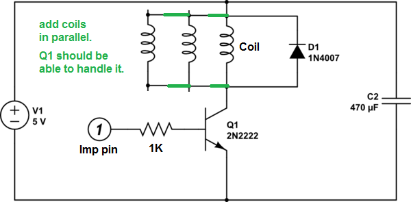
You can use an imp pin to drive the relay(s), or any 5V load, via a switching transistor (2N2222):