Can someone give me (a poor software engineer) a bit of a hand? I’m looking to build a device which can monitor whether a 120V household AC circuit is live or not. What I’d like to do is be able to log the date/time each time the circuit is energized, and each time it is de-energized.
There’s a bunch of ideas on how to do this, optocoupler, current transformer, use a cellphone charger on the same circuit (yielding +5V on USB when the circuit is energized), etc.
I’d appreciate a simple, concise explanation of exactly how to wire something up to do this. I’m likely to be able to figure out how to build it and write the software.
Note, I don’t care what the voltage is nor what the current draw is. I wouldn’t mind knowing, but that’s not the important part.
A bit more information first might be useful. Are you trying to determine if a particular outlet is energized, say, one that is controlled from a wall switch for example? Or, are you trying to determine if something you have plugged into a live outlet is turned on and drawing current? (It seems like the former, but I just wanted to clarify as it could impact what you’re looking for).
Also, would you be looking to plug something into an outlet to monitor, or would it need to indirectly sense (current sense for example) by perhaps going around the power cord of something you have plugged in?
Correct, the former. I’m interested in if the mains power is hot or not, not (necessarily) whether or how much is being drawn by the device plugged into the outlet.
I’d be happy with a invasive or non-invasive solution.
would you need something inline?
(i.e. the monitor is plugged into the outlet,
then something is plugged into the monitor)
if something is plugged into the outlet, is it
assured to be on (i.e. drawing current) if the
mains power is on?
Only reason for the questions is to determine the simplest approach for you, and if current or voltage monitoring would be more feasible. (The first question above would imply a possible voltage monitor, where the other question might suggest a current monitoring approach).
Inline is fine, but not a requirement. My assumption would be that using a current transformer would still require some in-line-ness (as the transformer needs to be around the hot or neutral, but not both – right?).
I believe that it would be fine to assume that if the mains are energized, the device being monitored (i.e., the device plugged into the switched outlet) would be drawing current. It’s a requirement that it work if the current draw requirement is low, but nonzero. (What’s “low”?)
Ok, I think that should be enough to go on … (or for others who have perhaps done this to also offer a response). I’ll take a look around at a couple of devices, but perhaps to get you started …
If have two outlets (both energized at the same time), your initial suggestion of perhaps using an inexpensive charger to provide a low voltage indication of the AC being on would be a good simple solution.
is a power strip that will energize a set of outlets if the control one is drawing power. I use this on my television. the TV is the master and my raspberry pi board is powered from one of the slaved outlets. Whenever I turn on the TV, the pi is booted.
With this idea you would next need to find a way to safely identify the fact that the outlets have been turned on. An easy way to do this is with an old cell phone charger. There is another outlet that is not controlled and this could be use to power an imp.
I realize you might want more of a DIY approach but this solution would be quite reliable. a thought.
@mjkuwp94’s solution won’t work. I need the data of when power is applied AND when power is lost.
@LarryJ’s first link, to someone else doing a similar thing, yielded a schematic … but which I don’t know exactly what to do with. See attached, what values do I use for R1, R2, C1, R3? Which Imp pin should I use (to wakeup, I need pin 1)? What do I need to do to get the Imp to wake on off-to-on and on-to-off?
Ok, that’s some good add’l info about your needs. For completeness, how are you planning to power the imp … battery, or will it be run off another (always on) power adapter?
Yes, pin 1 is the typical imp ‘power on’ detect pin, but can only detect a state change in one (i.e. low --> high) direction, so a little add’l circuitry would likely needed if you’re trying to detect on --> off as well as off --> on transitions.
(Things might get a bit easier if you weren’t running the imp off batteries, but just let us know your intended imp power scheme).
@adamgoldberg, do you mean that you need to know when there is a power outage? like when a tree falls on a power line? otherwise, that belkin product will work. It turns the load ON and it will turn it OFF. In my setup that keeps the Raspberry pi from being constantly on. The key benefit is that it gets the updates - which are loaded upon power-up/boot.
@adamgoldberg, do you mean that you need to know when there is a power outage?
No. I'm measuring the duty cycle of a device which is switched like a sump pump is, where the AC outlet is hot for a time, then not for a time. I need to take action when the off-to-on occurs and when the on-to-off occurs.
mjkuwp94:
How about a non-contacting sensor that uses a 555 timer chip?
http://www.circuitdiagram.org/non-contact-ac-voltage-detector.html
Well, that’s interesting, but… What if there’s other AC nearby? Also, why would I need the 555 at all, I don’t need a clock, I just need to know when the power comes and goes.
LarryJ:
Ok, that's some good add'l info about your needs. For completeness, how are you planning to power the imp .. battery, or will it be run off another (always on) power adapter?
Yes, pin 1 is the typical imp ‘power on’ detect pin, but can only detect a state change in one (i.e. low → high) direction, so a little add’l circuitry would likely needed if you’re trying to detect on → off as well as off → on transitions.
It doesn’t need to run on battery.
Can someone choose R1, R2, C1, R3 values (see above)? Please?
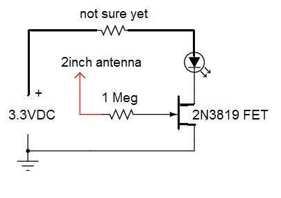
The 555 isn’t a clock (as in time) … it does the clean trigger to your pin when AC is detected. The antenna is a tiny wire about 2 inches long laying alongside the hot 120VAC. It will only detect what is right next to it.
I just thought it might be an idea not yet mentioned … I might try building one just to see how it works.
Another idea …
Glue an accelerometer to the outside of the device and detect when it is running by vibration, if it has some vibration or movement. That might also be a 3.3VDC powered device.
Ok, well, it’s easy enough to try, I suppose. But after omitting the LED and buzzer, do any R/C values change? Where does one connect the Imp pin 1 to?
Good question …
Now I’m thinking maybe another transistor instead of the 555 … just for a simple ON or OFF. Back to the drawing board. I’ll have to learn more about the 2N3819 FET
I have a need for the same thing as you … (non-invasive 120VAC detection on a cord). So I just ordered some parts from Mouser. In a couple of weeks I’ll come up with something (hopefully).