Here’s the use of a simple single rail-to-rail op-amp (rail to rail on both input and output is important for your application):
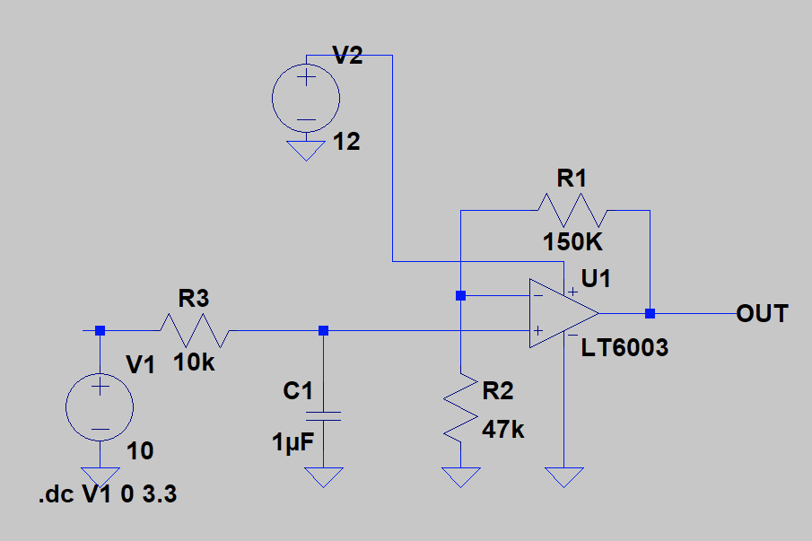
The part here is an LT one (not cheap) but they have nice free simulation software  … short circuit current is always >500uA so should drive your load fine (though the feedback network takes 50uA). There are cheaper options available too, you can certainly experiment. Note that you need a power supply of >=10v to run this from - here I’m using 12v.
The input on the left is a PWM, low pass filtered by R3/C1. This is a 100Hz filter, I’d suggest you run your PWM at 1kHz or higher which will still give you a huge amount of resolution (many thousands of steps).
The circuit multiplies by 15/4.7 = 3.19x so to get 10v out you’d need to put 3.13v in, or 0.95 as the PWM parameter for a 3v3 PWM. It’s linear across the whole range.
Depending on how far the signal is traveling, you may want to add some ESD diodes to the output too.