I need to generate a 0-10v analog signal to control some industrial equipment (fan and damper) with an IMP003. The specs seem to be a standard industrial 0-10v interface (not the current loop). I’m told that the impedance at the controller end is 21k and the current is 500ua. I’m struggling with how to generate this 0-10v signal simply and inexpensively.
I’ve looked at a number of op amp circuits, and sure, I can do that. But it increases my chip count and cost substantially and analog circuitry is not my strong point.
Has anyone implemented something simple and straightforward? It seems PWM is the way to go. But maybe there’s something I can do with the DAC. I’d also thought of using a digipot as a simple voltage divider on a 10vdc input but not sure that would work properly.
Suggestions, and examples would be really welcome.
I just noticed the PWM pulse might have to be >4.5V so, the imp pin output 3.3V might not be enough. Perhaps a transistor in-between to switch 3.3V to 5V for the pulse voltage?
Really you do need a buffer amp to make this a “stiff” output (though 500uA is a pretty weak load).
However, that’s pretty simple, and can be used to amplify your signal too. Yes you can use a filtered PWM as the input - this could give you more resolution than the DAC, at expensive of bandwidth - or the DAC on the imp.
I’ve looked at a number of schemes, one more complex than the other. EE’s sure can get wrapped up in detail. But none really impressed me as practical.
I need something simple and hopefully cheap that will allow me to provide this 0-10v signal under Imp control - reacting to sensor readings. I don’t need all that much resolution 8 bits is probably over-kill, 6 bits would be fine. But it is critical that I can a true 0v and 10v at either end of the spectrum.
I would appreciate some buffer amp recommendations that would work and some idea of how much pwm filtering I need to do in front of the amp.
I’m not looking for a separate component, as in mlseim’s suggestion. I need some circuitry I can incorporate into my current PCB design. My solution needs to be in a single package. (But thanks to mlseim for suggesting it.)
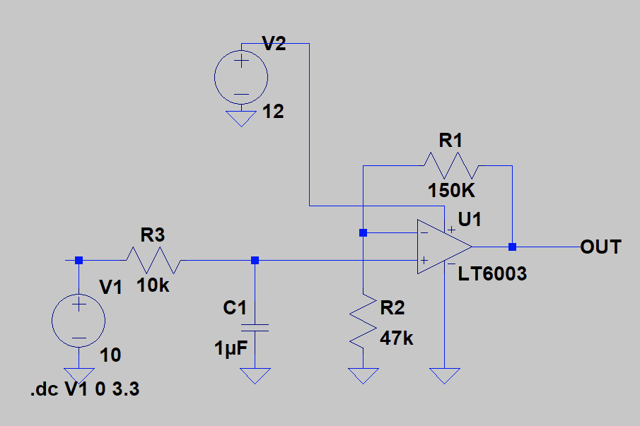
The part here is an LT one (not cheap) but they have nice free simulation software … short circuit current is always >500uA so should drive your load fine (though the feedback network takes 50uA). There are cheaper options available too, you can certainly experiment. Note that you need a power supply of >=10v to run this from - here I’m using 12v.
The input on the left is a PWM, low pass filtered by R3/C1. This is a 100Hz filter, I’d suggest you run your PWM at 1kHz or higher which will still give you a huge amount of resolution (many thousands of steps).
The circuit multiplies by 15/4.7 = 3.19x so to get 10v out you’d need to put 3.13v in, or 0.95 as the PWM parameter for a 3v3 PWM. It’s linear across the whole range.
Depending on how far the signal is traveling, you may want to add some ESD diodes to the output too.
It;s much simpler than what I’ve been looking at. Yes, the LT is a little pricey, but within parameters. Best part is that it won’t take up much board space.
So this looks like a great PWM solution. I’d still like to hear from others reading this with a different approach that might use fewer or less expensive components.
There are certainly other parts that offer rail to rail input and output, I just didn’t have much time to find parts. eg, this one looks possible too: http://www.ti.com/lit/ds/symlink/lmc7101.pdf
Hugo. Thanks again for taking the time to help out. That second chip looks good, and quite a bit less costly. Now that I know what I’m looking for, I’ll do a little more digging to see what else is out there.
Since I’m getting no other suggestions, it looks like PWM is the way to go. I had looked into the fixed frequency DAC to eliminate the need for input filtering on the op amp. (I haven’t worked with that feature yet.) It seems to require a continuous buffer blob feed, adding complexity to software just to avoid a couple of passive hardware components. Looks like going with the hardware is a good trade-off.
You don’t actually need ffdac unless you’re trying to change stuff really fast; you can just configure the pin as ANALOG_OUT and write to it to set a level - however, you only get 4096 levels in that case, whereas you can get much more resolution with PWM as you are trading off bandwidth for resolution.
In most cases I use simple MOSFET switch - typically industrial devices like frequency converters, soft-starters etc. have built PWM low pass filter and also are connected to 10V. Or you have potentiometer “style” input - GND, viper and +10V.
Solution really depend from device but it is very simple: PWM output (PWM frequency > 30 KHz) MOSFET (gate threshold <2V, like 2N7000) or ULN2003 chip) and low pass RC filter. You can build it all or just a part - as I have said: many industrial devices accept PWM, regulated 0…10V.
Thanks Peter. That’s a good idea, if it works for my situation. It’s a speed control for an industrial fan. I’ve had a devil of a time trying to get specs out of the manufacturer and the above are all I got. So I have no idea if their input is PWM tolerant, as you suggest.
As I understand your suggestion, the low pass filter is on the output of the MOSFET. So with a good filter, it should be pretty close to dc. Are you suggesting that some industrial controls require no filtering?
It certainly would be lower cost than the op amp solution.
I have regulated in such way ABB frequency converters (20KW), Siemens drives and so on. Even I have used such shematics in PID regulations for these drives (about 10ms response time) - all work nice. R=1K, C=1…10uF typically work fine (about 500 Hz PWM frequency) but smoothing, voltage drop (in case if PWM frequency is to high) and filter response time must be tested by load 20 K (approx what you have mentioned). You can play a bit around with imp’s PWM frequency.
Solution is simple and even there is PWM input. More problems generate 10V (typically I use 12V) small power supply. May be some cheap step-up DC-DC (from 3,3 or 5V to 10…12V) converter can help - there are plenty on eBay and Alibaba.
 … short circuit current is always >500uA so should drive your load fine (though the feedback network takes 50uA). There are cheaper options available too, you can certainly experiment. Note that you need a power supply of >=10v to run this from - here I’m using 12v.